PDFWAC 246-272B-06350
Drainfields.
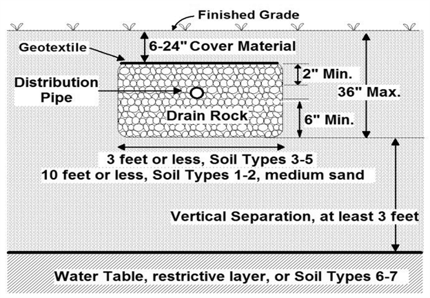
(1) Pressure distribution with timed dosing to the drainfield is required for all LOSS projects. A typical drainfield profile is shown in Figure 2 in this section.
(2) The drainfield area must be sufficient to allow installation of the required capacity and for a reserve area calculated using requirements in this section.
(3) The drainfield for a new LOSS must be located on the property served or within one-half mile or less from the new drainfield site property line to the closest point of the development property line.
(4) Any easements and right of way franchises must be obtained, recorded on the property title, and copies submitted to the department according to WAC 246-272B-04100 (1)(f).
(5) The design engineer shall not design or approve the installation of a drainfield as part of a LOSS where:
(a) The slope is greater than thirty percent or seventeen degrees;
(b) The area is subject to:
(i) Encroachment by buildings or other construction including, but not limited to, placement of power poles and underground utilities;
(ii) Cover by impervious material; or
(iii) Vehicular traffic.
(c) The reserve area is insufficient to treat and dispose of all of the design flow;
(d) The land is unstable;
(e) Surface drainage is directed toward the drainfield site; or
(f) Other activities or conditions identified by the department could adversely affect the soil or the performance of the LOSS.
(6) Except with the use of subsurface driplines or when treatment is provided consistent with subsection (16) or (17) of this section, drainfield components must be sized as follows:
(a) Hydraulic loading rates must not exceed the rates listed in WAC 246-272B-03400, Table 1;
(b) Calculation of the absorption area must be based on the design flow determined following requirements of WAC 246-272B-06150; and
(c) One hundred fifty percent of the required drainfield capacity must be constructed and sufficient area held in reserve to construct another fifty percent.
(7) Drainfield sizing when subsurface dripline is used must meet the requirements of WAC 246-272B-06650 (20) and (22).
(8) Drainfield pipe materials must meet the following minimum specifications:
(a) ASTM D2241-05 Class 200 or equivalent; or
(b) For schedule 40 and schedule 80 PVC, the material must meet ASTMD1785-06.
(9) A minimum of three equal-sized distribution sectors must be provided to allow for resting, emergency capacity, and repair capability.
(10) Dosing must automatically rotate among the active distribution sectors.
(11) The infiltrative surface must not be deeper than three feet below finished grade.
(12) The infiltrative surface must be constructed level.
(13) On sloping sites, the trenches and beds must run parallel to the natural ground contours.
(14) For drainfields using drain rock and distribution pipe, the following are required:
(a) A minimum of six inches of drain rock below the distribution pipe;
(b) A minimum of two inches of drain rock above the distribution pipe;
(c) A minimum of six inches of sidewall must be located in original undisturbed soil; and
(d) Six to twenty-four inches of cover material.
(15) For drainfields using trenches, the following minimum separations are required:
(a) Four and one-half feet between adjacent trench sidewalls; and
(b) Ten feet from the edge of one drainfield sector to the edge of an adjacent drainfield sector.
(16) For drainfields using beds, the following are required:
(a) Installation only in soil types 1 or 2, or in medium sands;
(b) Maximum bed width of ten feet; and
(c) Minimum separation between adjacent bed walls of ten feet.
(17) With documentation and justification from the design engineer, the department may authorize one of the following design changes for a LOSS that meets Treatment Level C or better and has a design flow of 14,500 gpd or less:
(a) The hydraulic loading rate in Table 1, WAC 246-272B-03400, may be increased:
(i) Up to a factor of two for soil types 2-4; or
(ii) Up to a factor of one and one-half for soil type 5;
(b) Vertical separation may be reduced as described in WAC 246-272B-06100; or
(c) The constructed drainfield capacity may be reduced from one hundred fifty percent to one hundred percent if the reserve area has the capacity to receive one hundred percent of the design flow.
(18) With documentation and justification from the design engineer, the department may authorize one of the following design changes for a LOSS that meets Treatment Level C or better and has a design flow greater than 14,500 gpd.
(a) The Table 1 hydraulic loading rate may be increased up to a factor of one and one-half for soil types 2-4;
(b) Vertical separation may be reduced as described in WAC 246-272B-06100; or
(c) The constructed drainfield capacity may be reduced from one hundred fifty percent to one hundred percent if the reserve area has the capacity to receive one hundred percent of the design flow.
(19) The department shall only approve one design change listed in subsections (17) or (18) of this section for any proposed LOSS.
(20) The reserve area for the drainfield must be calculated based on maximum hydraulic loading rates in Table 1 in WAC 246-272B-03400 and may not be reduced by the provisions listed in subsection (17) or (18) of this section.
Figure 2: Typical Pressure Distribution Drainfield Profile
 |
[Statutory Authority: RCW 70.118B.020. WSR 11-12-035, § 246-272B-06350, filed 5/25/11, effective 7/1/11.]