
PDFWAC 51-11R-40551
Table R405.4.2(1)—Specifications for the standard reference and proposed designs.
TABLE R405.4.2(1)
SPECIFICATIONS FOR THE STANDARD REFERENCE AND PROPOSED DESIGNS
BUILDING COMPONENT | STANDARD REFERENCE DESIGN | PROPOSED DESIGN |
Above-grade walls | Type: Mass wall if proposed wall is mass; otherwise wood frame. Gross area: Same as proposed U-factor: From Table R402.1.2 Solar absorptance = 0.75 Emittance = 0.90 | As proposed As proposed As proposed As proposed As proposed |
Below-grade walls | Type: Same as proposed Gross area: Same as proposed U-factor: From Table R402.1.2, with insulation layer on interior side of walls. | As proposed As proposed As proposed |
Above-grade floors | Type: Wood frame Gross area: Same as proposed U-factor: From Table R402.1.2 | As proposed As proposed As proposed |
Ceilings | Type: Wood frame Gross area: Same as proposed U-factor: From Table R402.1.2 | As proposed As proposed As proposed |
Roofs | Type: Composition shingle on wood sheathing Gross area: Same as proposed Solar absorptance = 0.75 Emittance = 0.90 | As proposed As proposed As proposed As proposed |
Attics | Type: Vented with aperture = 1 ft2 per 300 ft2 ceiling area | As proposed |
Foundations | Type: Same as proposed foundation wall area above and below-grade Soil characteristics: Same as proposed. | As proposed As proposed |
Opaque doors | Area: 40 ft2 Orientation: North U-factor: Same as fenestration from Table R402.1.2. | As proposed As proposed As proposed |
Vertical fenestration other than opaque doorsa | Total areah = (a) The proposed glazing area; where proposed glazing area is less than 15% of the conditioned floor area. (b) 15% of the conditioned floor area; where the proposed glazing area is 15% or more of the conditioned floor area. | As proposed |
Orientation: Equally distributed to four cardinal compass orientations (N, E, S & W). | As proposed | |
U-factor: From Table R402.1.2 | As proposed | |
SHGC: From Table R402.1.1 except that for climates with no requirement (NR) SHGC = 0.40 shall be used. | As proposed | |
Interior shade fraction: 0.92 - (0.21 × SHGC for the standard reference design) External shading: None | 0.92 - (0.21 × SHGC as proposed) As proposed | |
Skylights | None | As proposed |
Air exchange rate | Air leakage rate of 4 air changes per hour at a pressure of 0.2 inches w.g. (50 Pa). The mechanical ventilation rate shall be in addition to the air leakage rate and the same as in the proposed design, but no greater than 0.01 × CFA +7.5 × (Nbr + 1) where: CFA = conditioned floor area Nbr = number of bedrooms - The mechanical ventilation system type shall be the same as in the proposed design. Energy recovery shall not be assumed for mechanical ventilation. | As proposeda. The mechanical ventilation rateb shall be in addition to the air leakage rate and shall be as proposed. |
Mechanical ventilation | None, except where mechanical ventilation is specified by the proposed design, in which case: Annual vent fan energy use: kWh/yr = (1ef) × (0.0876 × CFA + 65.7 × (Nbr + 1) where: ef = the minimum fan efficacy from Table R403.6.1 corresponding to the system type at a flow rate of 0.01 × CFA + 7.5 × (Nbr + 1) CFA = conditioned floor area Nbr = number of bedrooms | As proposed |
Internal gains | IGain = 17,900 + 23.8 × CFA + 4104 × Nbr (Btu/day per dwelling unit) | Same as standard reference design |
Internal mass | An internal mass for furniture and contents of 8 pounds per square foot of floor area. | Same as standard reference design, plus any additional mass specifically designed as a thermal storage elementc but not integral to the building envelope or structure. |
Structural mass | For masonry floor slabs, 80% of floor area covered by R-2 carpet and pad, and 20% of floor directly exposed to room air. | As proposed |
For masonry basement walls, as proposed, but with insulation required by Table R402.1.2 located on the interior side of the walls. | As proposed | |
For other walls, for ceilings, floors, and interior walls, wood frame construction. | As proposed | |
Heating systemsd, e | The standard reference design shall be an air source heat pump meeting the requirements of Section C403 of the WSEC—Commercial Provisions. Capacity: Sized in accordance with Section R403.7 | As proposed |
Cooling systemsd, f | Same system type as proposed. Same system efficiency as required by prevailing minimum federal standard. Capacity: Sized in accordance with Section R403.7 | As proposed |
Service water heatingd, e, f, g | The standard reference design shall be a heat pump water heater meeting the efficiency standards of Table C404.2. Use, in units of gal/day = 25.5 + (8.5 x Nbr) Where Nbr = number of bedrooms | As proposed Use, in units of gal/day = 25.5 + (8.5 x Nbr) x (1 - HWDS) Where: Nbr= number of bedrooms HWDS = factor for the compactness of the hot water distribution system 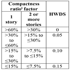 |
Thermal distribution systems | Duct insulation: From Section R403.3.3. Duct location: Same as proposed design. A thermal distribution system efficiency (DSE) of 0.93 shall be applied to both the heating and cooling system efficiencies for all systems. Exception: For nonducted heating and cooling systems that do not have a fan, the standard reference design distribution system efficiency (DSE) shall be 1. | Duct insulation: As proposed. Duct location: As proposed. As specified in Table R405.5.2(2). |
Thermostat | Type: Manual, cooling temperature setpoint = 75°F; Heating temperature setpoint = 72°F | Same as standard reference |
For SI: | 1 square foot = 0.93 m2, 1 British thermal unit = 1055 J, 1 pound per square foot = 4.88 kg/m2, 1 gallon (U.S.) = 3.785 L, °C = (°F-3)/1.8, 1 degree = 0.79 rad |
a | Where required by the code official, testing shall be conducted by an approved party. Hourly calculations as specified in the ASHRAE Handbook of Fundamentals, or the equivalent, shall be used to determine the energy loads resulting from infiltration. |
b | The combined air exchange rate for infiltration and mechanical ventilation shall be determined in accordance with Equation 43 of 2001 ASHRAE Handbook of Fundamentals, page 26.24 and the "Whole-house Ventilation" provisions of 2001 ASHRAE Handbook of Fundamentals, page 26.19 for intermittent mechanical ventilation. |
c | Thermal storage element shall mean a component not part of the floors, walls or ceilings that is part of a passive solar system, and that provides thermal storage such as enclosed water columns, rock beds, or phase-change containers. A thermal storage element must be in the same room as fenestration that faces within 15 degrees (0.26 rad) of true south, or must be connected to such a room with pipes or ducts that allow the element to be actively charged. |
d | For a proposed design with multiple heating, cooling or water heating systems using different fuel types, the applicable standard reference design system capacities and fuel types shall be weighted in accordance with their respective loads as calculated by accepted engineering practice for each equipment and fuel type present. |
e | For a proposed design without a proposed heating system, a heating system with the prevailing federal minimum efficiency shall be assumed for both the standard reference design and proposed design. |
f | For a proposed design home without a proposed cooling system, an electric air conditioner with the prevailing federal minimum efficiency shall be assumed for both the standard reference design and the proposed design. |
g | For a proposed design with a nonstorage-type water heater, a 40-gallon storage-type water heater with the prevailing federal minimum energy factor for the same fuel as the predominant heating fuel type shall be assumed. For the case of a proposed design without a proposed water heater, a 40-gallon storage-type water heater with the prevailing federal minimum efficiency for the same fuel as the predominant heating fuel type shall be assumed for both the proposed design and standard reference design. |
h | For residences with conditioned basements, R-2 and R-4 residences and townhouses, the following formula shall be used to determine fenestration area: |
AF = As x FA x F | ||
Where: | ||
AF | = | Total fenestration area. |
As | = | Standard reference design total fenestration area. |
FA | = | (Above-grade thermal boundary gross wall area)/(above-grade boundary wall area + 0.5 x below-grade boundary wall area). |
F | = | (Above-grade thermal boundary wall area)/(above-grade thermal boundary wall area + common wall area) or 0.56, whichever is greater. |
and where: | ||
Thermal boundary wall is any wall that separates conditioned space from unconditioned space or ambient conditions. | ||
Above-grade thermal boundary wall is any thermal boundary wall component not in contact with soil. | ||
Below-grade boundary wall is any thermal boundary wall in soil contact. | ||
Common wall area is the area of walls shared with an adjoining dwelling unit. | ||
L and CFA are in the same units. | ||
i | The factor for the compactness of the hot water distribution system is the ratio of the area of the rectangle that bounds the source of hot water and the fixtures that it serves (the "hot water rectangle") divided by the floor area of the dwelling. |
1. Sources of hot water include water heaters, or in multifamily buildings with central water heating systems, circulation loops, or electric heat traced pipes. | |
2. The hot water rectangle shall include the source of hot water and the points of termination of all hot water fixture supply piping. | |
3. The hot water rectangle shall be shown on the floor plans and the area shall be computed to the nearest square foot. | |
4. Where there is more than one water heater and each water heater serves different plumbing fixtures and appliances, it is permissible to establish a separate hot water rectangle for each hot water distribution system and add the area of these rectangles together to determine the compactness ratio. | |
5. The basement or attic shall be counted as a story when it contains the water heater. | |
6. Compliance shall be demonstrated by providing a drawing on the plans that shows the hot water distribution system rectangle(s), comparing the area of the rectangle(s) to the area of the dwelling and identifying the appropriate compactness ratio and HWDS factor. |
[Statutory Authority: RCW 19.27A.020, 19.27A.045, 19.27A.160, and chapter 19.27A RCW. WSR 24-03-084, § 51-11R-40551, filed 1/16/24, effective 3/15/24; WSR 23-02-060, 23-12-102, and 23-20-022, § 51-11R-40551, filed 1/3/23, 6/7/23, and 9/25/23, effective 3/15/24. Statutory Authority: RCW 19.27A.045 and chapter 19.27A RCW. WSR 20-21-081, § 51-11R-40551, filed 10/19/20, effective 2/1/21. Statutory Authority: RCW 19.27A.020, 19.27A.045, 19.27A.160 and chapter 19.27 RCW. WSR 20-01-047, § 51-11R-40551, filed 12/9/19, effective 7/1/20. Statutory Authority: RCW 19.27A.020, 19.27A.045, 19.27A.160, and 19.27.074. WSR 16-02-127, § 51-11R-40551, filed 1/6/16, effective 7/1/16. Statutory Authority: RCW 19.27A.020, 19.27A.045 and chapters 19.27 and 34.05 RCW. WSR 13-04-055, § 51-11R-40551, filed 2/1/13, effective 7/1/13.]