
PDFWAC 296-24-862
Nonmandatory appendices.
Nonmandatory Appendix A to Part J-2, Scaffold Specifications.
This Appendix provides nonmandatory guidelines to assist employers in complying with the requirements of Part J-2 of this chapter. An employer may use these guidelines and tables as a starting point for designing scaffold systems. However, the guidelines do not provide all the information necessary to build a complete system, and the employer is still responsible for designing and assembling these components in such a way that the completed system will meet the requirements of WAC 296-24-86010(1). Scaffold components which are not selected and loaded in accordance with this Appendix, and components for which no specific guidelines or tables are given in this Appendix (e.g., joints, ties, components for wood pole scaffolds more than 60 feet in height, components for heavy-duty horse scaffolds, components made with other materials, and components with other dimensions, etc.) must be designed and constructed in accordance with the capacity requirements of WAC 296-24-86010(1), and loaded in accordance with WAC 296-24-86010 (4)(a).
Index to Appendix A for Part J-2
1. General guidelines and tables.
2. Specific guidelines and tables.
(a) Pole scaffolds:
Single-pole wood pole scaffolds.
Independent wood pole scaffolds.
(b) Tube and coupler scaffolds.
(c) Fabricated frame scaffolds.
(d) Plasterers', decorators' and large area scaffolds.
(e) Bricklayers' square scaffolds.
(f) Horse scaffolds.
(g) Form scaffolds and carpenters' bracket scaffolds.
(h) Roof bracket scaffolds.
(i) Outrigger scaffolds (one level).
(j) Pump jack scaffolds.
(k) Ladder jack scaffolds.
(l) Window jack scaffolds.
(m) Crawling boards (chicken ladders).
(n) Step, platform and trestle ladder scaffolds.
(o) Single-point adjustable suspension scaffolds.
(p) Two-point adjustable suspension scaffolds.
(q)(1) Stonesetters' multipoint adjustable suspension scaffolds.
(q)(2) Masons' multipoint adjustable suspension scaffolds.
(r) Catenary scaffolds.
(s) Float (ship) scaffolds.
(t) Interior hung scaffolds.
(u) Needle beam scaffolds.
(v) Multilevel suspension scaffolds.
(w) Mobile scaffolds.
(x) Repair bracket scaffolds.
(y) Stilts.
(z) Tank builders' scaffolds.
1. General guidelines and tables.
(a) The following tables, and the tables in Part 2—Specific guidelines and tables, assume that all load-carrying timber members (except planks) of the scaffold are a minimum of 1,500 lb-f/in(2) (stress grade) construction grade lumber. All dimensions are nominal sizes as provided in the American Softwood Lumber Standards, dated January 1970, except that, where rough sizes are noted, only rough or undressed lumber of the size specified will satisfy minimum requirements.
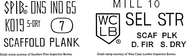
(b) Solid sawn wood used as scaffold planks must be selected for such use following the grading rules established by a recognized lumber grading association or by an independent lumber grading inspection agency. Such planks must be identified by the grade stamp of such association or agency. The association or agency and the grading rules under which the wood is graded must be certified by the Board of Review, American Lumber Standard Committee, as set forth in the American Softwood Lumber Standard of the U.S. Department of Commerce.
(i) Allowable spans must be determined in compliance with the National Design Specification for Wood Construction published by the National Forest Products Association; paragraph 5 of ANSI A10.8-1988 Scaffolding-Safety Requirements published by the American National Standards Institute; or for 2 x 10 inch (nominal) or 2 x 9 inch (rough) solid sawn wood planks, as shown in the following table:
Maximum intended nominal load (lb/ft2) | Maximum permissible span using full thickness undressed lumber (ft) | Maximum permissible span using nominal thickness lumber (ft) |
25 | 10 | 8 |
50 | 8 | 6 |
75 | 6 |
(ii) The maximum permissible span for 1 1/4 x 9-inch or wider wood plank of full thickness with a maximum intended load of 50 lb/ft.(2) must be 4 feet.
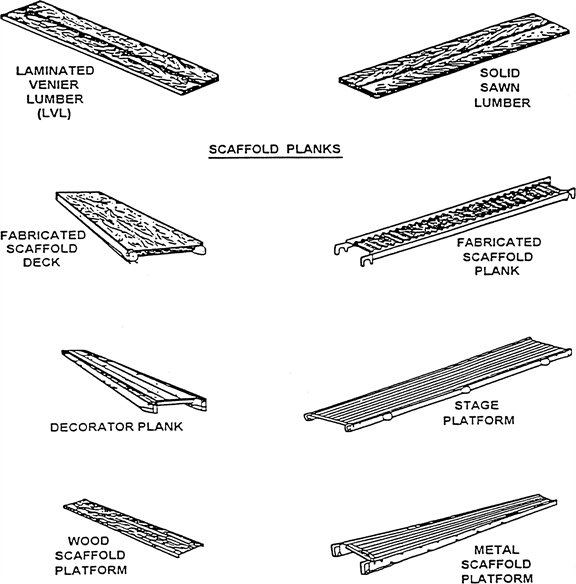
(c) Fabricated planks and platforms may be used in lieu of solid sawn wood planks. Maximum spans for such units must be as recommended by the manufacturer based on the maximum intended load being calculated as follows:
Rated load capacity | Intended load |
Light-duty | *25 pounds per square foot applied uniformly over the entire span area. |
Medium-duty | *50 pounds per square foot applied uniformly over the entire span area. |
Heavy-duty | *75 pounds per square foot applied uniformly over the entire span area. |
One-person | *250 pounds placed at the center of the span (total 250 pounds). |
Two-person | *250 pounds placed 18 inches to the left and right of the center of the span (total 500 pounds). |
Three-person | *250 pounds placed at the center of the span and 250 pounds placed 18 inches to the left and right of the center of the span (total 750 pounds). |
Note: Platform units used to make scaffold platforms intended for light-duty use must be capable of supporting at least 25 pounds per square foot applied uniformly over the entire unit-span area, or a 250-pound point load placed on the unit at the center of the span, whichever load produces the greater shear force.
(d) Guardrails must be as follows:
(i) Toprails must be equivalent in strength to 2 inch by 4 inch lumber; or
1 1/4 inch x 1/8 inch structural angle iron; or
1 inch x .070 inch wall steel tubing; or 1.990 inch x .058 inch wall aluminum tubing.
(ii) Midrails must be equivalent in strength to 1 inch by 6 inch lumber; or
1 1/4 inch x 1 1/4 inch x 1/8 inch structural angle iron; or
1 inch x .070 inch wall steel tubing; or
1.990 inch x .058 inch wall aluminum tubing.
(iii) Toeboards must be equivalent in strength to 1 inch by 4 inch lumber; or
1 1/4 inch x 1 1/4 inch structural angle iron; or
1 inch x .070 inch wall steel tubing; or
1.990 inch x .058 inch wall aluminum tubing.
(iv) Posts must be equivalent in strength to 2 inch by 4 inch lumber; or
1 1/4 inch x 1 1/4 inch x 1/8 structural angle iron; or
1 inch x .070 inch wall steel tubing; or
1.990 inch x .058 inch wall aluminum tubing.
(v) Distance between posts must not exceed 8 feet.
(e) Overhead protection must consist of 2 inch nominal planking laid tight, or 3/4-inch plywood.
(f) Screen installed between toeboards and midrails or toprails must consist of No. 18 gauge U.S. Standard wire one inch mesh.
2. Specific guidelines and tables.
(a) Pole scaffolds.
Single Pole Wood Pole Scaffolds | ||||
Light duty up to 20 feet high | Light duty up to 60 feet high | Medium duty up to 60 feet high | Heavy duty up to 60 feet high | |
Maximum intended load (lbs/ft2) | 25 | 25 | 50 | 75 |
Poles or uprights | 2 x 4 in. | 4 x 4 in. | 4 x 4 in. | 4 x 6 in. |
Maximum pole spacing (longitudinal) | 6 feet | 10 feet | 8 feet | 6 feet |
Maximum pole spacing (transverse) | 5 feet | 5 feet | 5 feet | 5 feet |
Runners | 1 x 4 in. | 1 1/4 x 9 in. | 2 x 10 in. | 2 x 10 in. |
Bearers and maximum spacing of bearers: 3 feet | 2 x 4 in. | 2 x 4 in. | 2 x 10 in. or 3 x 4 in. | 2 x 10 in. or 3 x 5 in. |
5 feet | 2 x 6 in. or 3 x 4 in. | 2 x 6 in. or 3 x 4 in. (rough) | 2 x 10 in. or 3 x 4 in. | 2 x 10 in. or 3 x 5 in. |
6 feet | — | — | 2 x 10 in. or 3 x 4 in. | 2 x 10 in. or 3 x 5 in. |
8 feet | — | — | 2 x 10 in. or 3 x 4 in. | |
Planking | 1 1/4 x 9 in. | 2 x 10 in. | 2 x 10 in. | 2 x 10 in. |
Maximum vertical spacing of horizontal members | 7 feet | 9 feet | 7 feet | 6 ft. 6 in. |
Bracing horizontal | 1 x 4 in. | 1 x 4 in. | 1 x 6 in. or 1 1/4 x 4 in. | 2 x 4 in. |
Bracing diagonal | 1 x 4 in. | 1 x 4 in. | 1 x 4 in. | 2 x 4 in. |
Tie-ins | 1 x 4 in. | 1 x 4 in. | 1 x 4 in. | 1 x 4 in. |
Note: All members except planking are used on edge. All wood bearers must be reinforced with 3/16 x 2 inch steel strip, or the equivalent, secured to the lower edges for the entire length of the bearer.
Independent Wood Pole Scaffolds | ||||
Light duty up to 20 feet high | Light duty up to 60 feet high | Medium duty up to 60 feet high | Heavy duty up to 60 feet high | |
Maximum intended load | 25 lbs/ft2 | 25 lbs/ft2 | 50 lbs/ft2 | 75 lbs/ft2 |
Poles or uprights | 2 x 4 in. | 4 x 4 in. | 4 x 4 in. | 4 x 4 in. |
Maximum pole spacing (longitudinal) | 6 feet | 10 feet | 8 feet | 6 feet |
Maximum (transverse) | 6 feet | 10 feet | 8 feet | 8 feet |
Runners | 1 1/4 x 4 in. | 1 1/4 x 9 in. | 2 x 10 in. | 2 x 10 in. |
Bearers and maximum spacing of bearers: 3 feet | 2 x 4 in. | 2 x 4 in. | 2 x 10 in. (rough) | 2 x 10 in. |
6 feet | 2 x 6 in. or 3 x 4 in. | 2 x 10 in. (rough) or 3 x 8 in. | 2 x 10 in. | 2 x 10 in. (rough) |
8 feet | 2 x 6 in. or 3 x 4 in. | 2 x 10 in. (rough) or 3 x 8 in. | 2 x 10 in. | |
10 feet | 3 x 4 in. | 2 x 6 in. (rough) or 3 x 3 in. | 2 x 10 in. | |
Planking | 1 1/4 x 9 in. | 2 x 10 in. | 2 x 10 in. | 2 x 10 in. |
Maximum vertical spacing of horizontal members | 7 feet | 7 feet | 6 feet | 6 feet |
Bracing horizontal | 1 x 4 in. | 1 x 4 in. | 1 x 6 in. or 1 1/4 x 4 in. | 2 x 4 in. |
Bracing diagonal | 1 x 4 in. | 1 x 4 in. | 1 x 4 in. | 2 x 4 in. |
Tie-ins | 1 x 4 in. | 1 x 4 in. | 1 x 4 in. | 1 x 4 in. |
Note: All members except planking are used on edge. All wood bearers must be reinforced with 3/16 x 2 inch steel strip, or the equivalent, secured to the lower edges for the entire length of the bearer.
(b) Tube and coupler scaffolds.
Minimum Size of Members | |||
Light duty | Medium duty | Heavy duty | |
Maximum intended load | 25 lbs/ft2 | 50 lbs/ft2 | 75 lbs/ft2 |
Posts, runners and braces | Nominal 2 in. (1.90 inches) OD steel tube or pipe. | Nominal 2 in. (1.90 inches) OD steel tube or pipe. | Nominal 2 in. (1.90 inches) OD steel tube or pipe. |
Bearers | Nominal 2 in. (1.90 inches) OD steel tube or pipe and a maximum post spacing of 4 ft. x 10 ft. | Nominal 2 in. (1.90 inches) OD steel tube or pipe and a maximum post spacing of 4 ft. x 7 ft. or Nominal 2 1/2 in. (2.375 in.) OD steel tube or pipe and a maximum post spacing of 6 ft. x 8 ft. (*). | Nominal 2 1/2 in. (2.375 in.) OD steel tube or pipe and a maximum post spacing of 6 ft. x 6 ft. |
Maximum runner spacing vertically | 6 ft. 6 in. | 6 ft. 6 in. | 6 ft. 6 in. |
(*) Bearers must be installed in the direction of the shorter dimension.
Note: Longitudinal diagonal bracing must be installed at an angle of 45 deg. (+/- 5 deg.).
Maximum Number of Planked Levels
Maximum number of
additional planked levels
Light duty | Medium duty | Heavy duty | Maximum height of scaffold (in feet) | |
Duty Number of Working Levels: | ||||
1 | 16 | 11 | 6 | 125 |
2 | 11 | 1 | 0 | 125 |
3 | 6 | 0 | 0 | 125 |
4 | 1 | 0 | 0 | 125 |
(c) Fabricated frame scaffolds. Because of their prefabricated nature, no additional guidelines or tables for these scaffolds are being adopted in this Appendix.
(d) Plasterers', decorators', and large area scaffolds. The guidelines for pole scaffolds or tube and coupler scaffolds (Appendix A (a) and (b)) may be applied.
(e) Bricklayers' square scaffolds.
Maximum intended load: 50 lb/ft.(2)(*)
Footnote(*): The squares must be set not more than 8 feet apart for light duty scaffolds and not more than 5 feet apart for medium duty scaffolds.
Maximum width: 5 ft.
Maximum height: 5 ft.
Gussets: 1 x 6 in.
Braces: 1 x 8 in.
Legs: 2 x 6 in.
Bearers (horizontal members): 2 x 6 in.
(f) Horse scaffolds.
Maximum intended load (light duty): 25 lb/ft.(2)(**)
Footnote(**): Horses must be spaced not more than 8 feet apart for light duty loads, and not more than 5 feet apart for medium duty loads.
Maximum intended load (medium duty): 50 lb/ft.(2)(**)
Footnote(**): Horses must be spaced not more than 8 feet apart for light duty loads, and not more than 5 feet apart for medium duty loads.
Horizontal members or bearers:
Light duty: 2 x 4 in.
Medium duty: 3 x 4 in.
Legs: 2 x 4 in.
Longitudinal brace between legs: 1 x 6 in.
Gusset brace at top of legs: 1 x 8 in.
Half diagonal braces: 2 x 4 in.
(g) Form scaffolds and carpenters' bracket scaffolds.
(1) Brackets must consist of a triangular-shaped frame made of wood with a cross-section not less than 2 inches by 3 inches, or of 1 1/4 inch x 1 1/4 inch x 1/8 inch structural angle iron.
(2) Bolts used to attach brackets to structures must not be less than 5/8 inches in diameter.
(3) Maximum bracket spacing must be 8 feet on centers.
(4) No more than two employees must occupy any given 8 feet of a bracket or form scaffold at any one time. Tools and materials must not exceed 75 pounds in addition to the occupancy.
(5) Wooden figure-four scaffolds:
Maximum intended load: 25 lb/ft.(2)
Uprights: 2 x 4 in. or 2 x 6 in.
Bearers (two): 1 x 6 in.
Braces: 1 x 6 in.
Maximum length of bearers (unsupported): 3 ft. 6 in.
(i) Outrigger bearers must consist of two pieces of 1 x 6 inch lumber nailed on opposite sides of the vertical support.
(ii) Bearers for wood figure-four brackets must project not more than 3 feet 6 inches from the outside of the form support, and must be braced and secured to prevent tipping or turning. The knee or angle brace must intersect the bearer at least 3 feet from the form at an angle of approximately 45 degrees, and the lower end must be nailed to a vertical support.
(6) Metal bracket scaffolds:
Maximum intended load: 25 lb/ft.(2)
Uprights: 2 x 4 inch
Bearers: As designed.
Braces: As designed.
(7) Wood bracket scaffolds:
Maximum intended load: 25 lb/ft.(2)
Uprights: 2 x 4 in. or 2 x 6 in.
Bearers: 2 x 6 in.
Maximum scaffold width: 3 ft. 6 in.
Braces: 1 x 6 in.
(h) Roof bracket scaffolds. No specific guidelines or tables are given.
(i) Outrigger scaffolds (single level). No specific guidelines or tables are given.
(j) Pump jack scaffolds. Wood poles must not exceed 30 feet in height. Maximum intended load — 500 lbs between poles; applied at the center of the span. Not more than two employees must be on a pump jack scaffold at one time between any two supports. When 2 x 4's are spliced together to make a 4 x 4 inch wood pole, they must be spliced with "10 penny" common nails no more than 12 inches center to center, staggered uniformly from the opposite outside edges.
(k) Ladder jack scaffolds. Maximum intended load — 25 lb/ft(2). However, not more than two employees must occupy any platform at any one time. Maximum span between supports must be 8 feet.
(l) Window jack scaffolds. Not more than one employee must occupy a window jack scaffold at any one time.
(m) Crawling boards (chicken ladders). Crawling boards must be not less than 10 inches wide and 1 inch thick, with cleats having a minimum 1 x 1 1/2 inch cross-sectional area. The cleats must be equal in length to the width of the board and spaced at equal intervals not to exceed 24 inches.
(n) Step, platform, and trestle ladder scaffolds. No additional guidelines or tables are given.
(o) Single-point adjustable suspension scaffolds. Maximum intended load — 250 lbs. Wood seats for boatswains' chairs must be not less than 1 inch thick if made of nonlaminated wood, or 5/8 inches thick if made of marine quality plywood.
(p) Two-point adjustable suspension scaffolds.
(1) In addition to direct connections to buildings (except window cleaners' anchors) acceptable ways to prevent scaffold sway include angulated roping and static lines. Angulated roping is a system of platform suspension in which the upper wire rope sheaves or suspension points are closer to the plane of the building face than the corresponding attachment points on the platform, thus causing the platform to press against the face of the building. Static lines are separate ropes secured at their top and bottom ends closer to the plane of the building face than the outermost edge of the platform. By drawing the static line taut, the platform is drawn against the face of the building.
(2) On suspension scaffolds designed for a working load of 500 pounds, no more than two employees must be permitted on the scaffold at one time. On suspension scaffolds with a working load of 750 pounds, no more than three employees must be permitted on the scaffold at one time.
(3) Ladder-type platforms. The side stringer must be of clear straight-grained spruce. The rungs must be of straight-grained oak, ash, or hickory, at least 1 1/8 inches in diameter, with 7/8 inch tenons mortised into the side stringers at least 7/8 inch. The stringers must be tied together with tie rods not less than 1/4 inch in diameter, passing through the stringers and riveted up tight against washers on both ends. The flooring strips must be spaced not more than 5/8 inch apart, except at the side rails where the space may be 1 inch. Ladder-type platforms must be constructed in accordance with the following table:
Schedule for Ladder-Type Platforms
Length of Platform | 12 feet | 14 & 16 feet | 18 & 20 feet |
Side stringers, minimum cross section (finished sizes): | |||
At ends | 1 3/4 x 2 3/4 in. | 1 3/4 x 2 3/4 in. | 1 3/4 x 3 in. |
At middle | 1 3/4 x 3 3/4 in. | 1 3/4 x 3 3/4 in. | 1 3/4 x 4 |
Reinforcing strip (minimum) | A 1/8 x 7/8 inch steel reinforcing strip must be attached to the side or underside, full length. | ||
Rungs | Rungs must be 1 1/8 inch minimum diameter with at least 7/8 inch in diameter tenons, and the maximum spacing must be 12 inches to center. | ||
Tie rods: Number (minimum) | 3 | 4 | 4 |
Diameter (minimum) | 1/4 inch | 1/4 inch | 1/4 inch |
Flooring, minimum finished size | 1/2 x 2 3/4 in. | 1/2 x 2 3/4 in. | 1/2 x 2 3/4 in. |
Length of Platform | 22 & 24 ft. | 28 & 30 ft. | |
Side stringers, minimum cross section (finished sizes): | |||
At ends | 1 3/4 x 3 in. | 1 3/4 x 3 1/2 in. | |
At middle | 1 3/4 x 4 1/4 in. | 1 3/4 x 5 in. | |
Reinforcing strip (minimum) | A 1/8 x 7/8 inch steel reinforcing strip must be attached to the side or underside, full length. | ||
Rungs | Rungs must be 1 1/8 inch minimum diameter with at least 7/8 inch in diameter with at least 7/8 inch in diameter tenons, and the maximum spacing must be 12 inches to center. | ||
Tie rods: Number (minimum) | 5 | 6 | |
Diameter (minimum) | 1/4 in. | 1/4 in. | |
Flooring, minimum finished size | 1/2 x 2 3/4 in. | 1/2 x 2 3/4 in. | |
(4) Plank-type platforms. Plank-type platforms must be composed of not less than nominal 2 x 8 inch unspliced planks, connected together on the underside with cleats at intervals not exceeding 4 feet, starting 6 inches from each end. A bar or other effective means must be securely fastened to the platform at each end to prevent the platform from slipping off the hanger. The span between hangers for plank-type platforms must not exceed 10 feet.
(5) Beam-type platforms. Beam platforms must have side stringers of lumber not less than 2 x 6 inches set on edge. The span between hangers must not exceed 12 feet when beam platforms are used. The flooring must be supported on 2 x 6 inch cross beams, laid flat and set into the upper edge of the stringers with a snug fit, at intervals of not more than 4 feet, securely nailed to the cross beams. Floor-boards must not be spaced more than 1/2 inch apart.
(q)(1) Multipoint adjustable suspension scaffolds and stonesetters' multipoint adjustable suspension scaffolds. No specific guidelines or tables are given for these scaffolds.
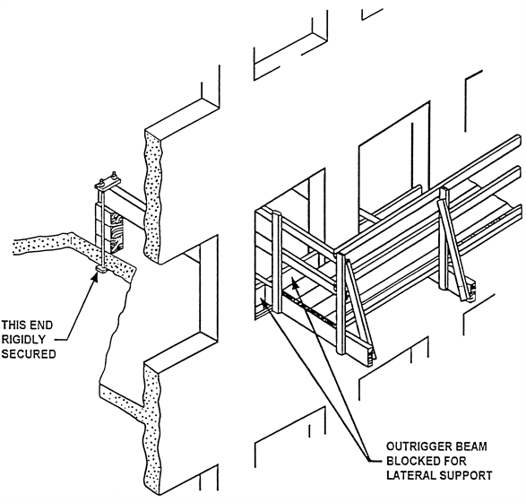
(q)(2) Masons' multipoint adjustable suspension scaffolds. Maximum intended load — 50 lb/ft(2). Each outrigger beam must be at least a standard 7 inch, 15.3 pound steel I-beam, at least 15 feet long. Such beams must not project more than 6 feet 6 inches beyond the bearing point. Where the overhang exceeds 6 feet 6 inches, outrigger beams must be composed of stronger beams or multiple beams.
(r) Catenary scaffolds.
(1) Maximum intended load — 500 lbs.
(2) Not more than two employees must be permitted on the scaffold at one time.
(3) Maximum capacity of come-along must be 2,000 lbs.
(4) Vertical pickups must be spaced not more than 50 feet apart.
(5) Ropes must be equivalent in strength to at least 1/2 inch (1.3 cm) diameter improved plow steel wire rope.
(s) Float (ship) scaffolds.
(1) Maximum intended load — 750 lbs.
(2) Platforms must be made of 3/4 inch plywood, equivalent in rating to American Plywood Association Grade B-B, Group I, Exterior.
(3) Bearers must be made from 2 x 4 inch, or 1 x 10 inch rough lumber. They must be free of knots and other flaws.
(4) Ropes must be equivalent in strength to at least 1 inch (2.5 cm) diameter first grade manila rope.
(t) Interior hung scaffolds.
Bearers (use on edge): 2 x 10 in.
Maximum intended load: Maximum span
25 lb/ft.(2): 10 ft.
50 lb/ft.(2): 10 ft.
75 lb/ft.(2): 7 ft.
(u) Needle beam scaffolds.
Maximum intended load: 25 lb/ft.(2)
Beams: 4 x 6 in.
Maximum platform span: 8 ft.
Maximum beam span: 10 ft.
(1) Ropes must be attached to the needle beams by a scaffold hitch or an eye splice. The loose end of the rope must be tied by a bowline knot or by a round turn and a half hitch.
(2) Ropes must be equivalent in strength to at least 1 inch (2.5 cm) diameter first grade manila rope.
(v) Multilevel suspension scaffolds. No additional guidelines or tables are being given for these scaffolds.
(w) Mobile scaffolds. Stability test as described in the ANSI A92 series documents, as appropriate for the type of scaffold, can be used to establish stability for the purpose of WAC 296-24-86015 (23)(f)(ii).
(x) Repair bracket scaffolds. No additional guidelines or tables are being given for these scaffolds.
(y) Stilts. No specific guidelines or tables are given.
(z) Tank builder's scaffold.
(1) The maximum distance between brackets to which scaffolding and guardrail supports are attached must be no more than 10 feet 6 inches.
(2) Not more than three employees must occupy a 10 feet 6 inch span of scaffold planking at any time.
(3) A taut wire or synthetic rope supported on the scaffold brackets must be installed at the scaffold plank level between the innermost edge of the scaffold platform and the curved plate structure of the tank shell to serve as a safety line in lieu of an inner guardrail assembly where the space between the scaffold platform and the tank exceeds 12 inches (30.48 cm). In the event the open space on either side of the rope exceeds 12 inches (30.48 cm), a second wire or synthetic rope appropriately placed, or guardrails in accordance with WAC 296-24-86010 (7)(d), must be installed in order to reduce that open space to less than 12 inches (30.48 cm).
(4) Scaffold planks of rough full-dimensioned 2-inch (5.1 cm) x 12-inch (30.5 cm) Douglas Fir or Southern Yellow Pine of Select Structural Grade must be used. Douglas Fir planks must have a fiber stress of at least 1900 lb/in(2) (130,929 n/cm(2)) and a modulus of elasticity of at least 1,900,000 lb/in(2) (130,929,000 n/cm(2)), while Yellow Pine planks must have a fiber stress of at least 2500 lb/in(2) (172,275 n/cm(2)) and a modulus of elasticity of at least 2,000,000 lb/in(2) (137,820,000 n/cm(2)).
(5) Guardrails must be constructed of a taut wire or synthetic rope, and must be supported by angle irons attached to brackets welded to the steel plates. These guardrails must comply with WAC 296-24-86010 (7)(d) guardrail supports must be located at no greater than 10 feet 6 inch intervals.
Nonmandatory Appendix C to Part J-2, List of National Consensus Standards.
ANSI/SIA A92.2-1990 Vehicle-Mounted Elevating and Rotating Aerial Devices
ANSI/SIA A92.3-1990 Manually Propelled Elevating Aerial Platforms
ANSI/SIA A92.5-1990 Boom Supported Elevating Work Platforms
ANSI/SIA A92.6-1990 Self-Propelled Elevating Work Platforms
ANSI/SIA A92.7-1990 Airline Ground Support Vehicle-Mounted Vertical Lift Devices
ANSI/SIA A92.8-1993 Vehicle-Mounted Bridge Inspection and Maintenance Devices
ANSI/SIA A92.9-1993 Mast-Climbing Work Platforms
Nonmandatory Appendix D to Part J-2, List of Training Topics for Scaffold Erectors and Dismantlers.
This Appendix D is provided to serve as a guide to assist employers when evaluating the training needs of employees erecting or dismantling supported scaffolds.
The Agency believes that employees erecting or dismantling scaffolds should be trained in the following topics:
*General Overview of Scaffolding
*regulations and standards
*erection/dismantling planning
*PPE and proper procedures
*fall protection
*materials handling
*access
*working platforms
*foundations
*guys, ties and braces
*Tubular Welded Frame Scaffolds
*specific regulations and standards
*components
*parts inspection
*erection/dismantling planning
*guys, ties and braces
*fall protection
*general safety
*access and platforms
*erection/dismantling procedures
*rolling scaffold assembly
*putlogs
*Tube and Clamp Scaffolds
*specific regulations and standards
*components
*parts inspection
*erection/dismantling planning
*guys, ties and braces
*fall protection
*general safety
*access and platforms
*erection/dismantling procedures
*buttresses, cantilevers, & bridges
*System Scaffolds
*specific regulations and standards
*components
*parts inspection
*erection/dismantling planning
*guys, ties and braces
*fall protection
*general safety
*access and platforms
*erection/dismantling procedures
*buttresses, cantilevers, & bridges
Scaffold erectors and dismantlers should all receive the general overview, and, in addition, specific training for the type of supported scaffold being erected or dismantled.
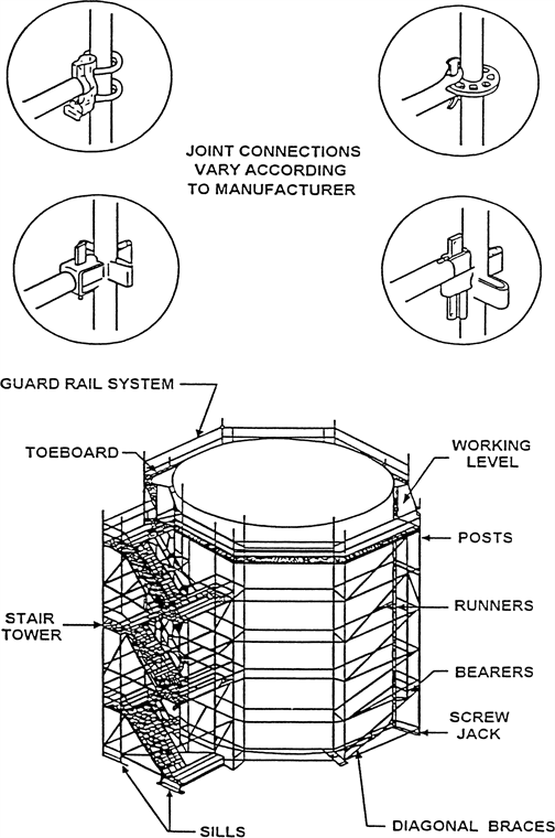
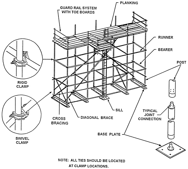
Nonmandatory Appendix E to Part J-2, Drawings and Illustrations.
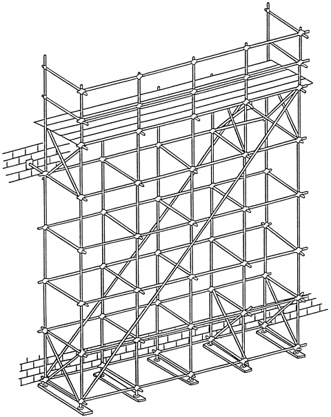
This Appendix provides drawings of particular types of scaffolds and scaffold components, and graphic illustrations of bracing patterns and tie spacing patterns.
This Appendix is intended to provide visual guidance to assist the user in complying with the requirements of Part J-2, chapter 296-24 WAC.
BRACING-TUBE & COUPLER SCAFFOLDS
 |
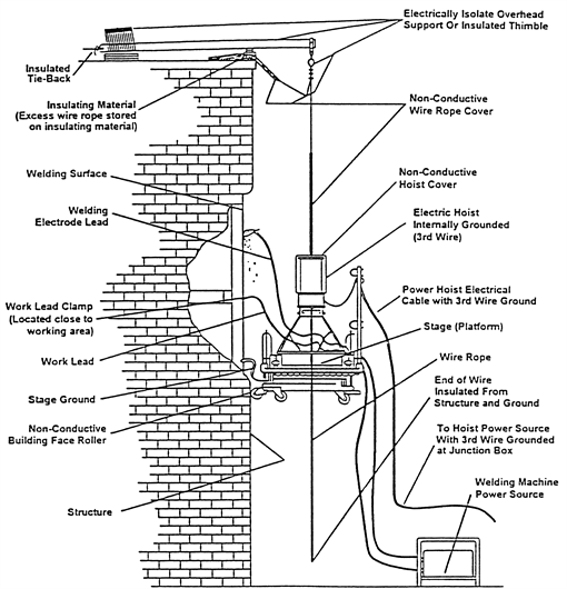
SUSPENDED SCAFFOLD PLATFORM WELDING PRECAUTIONS
 |
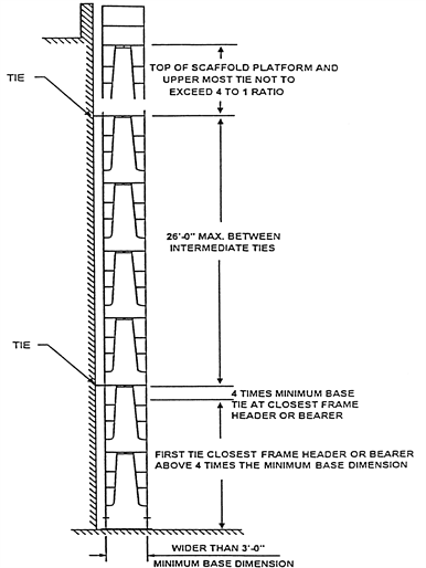
MAXIMUM VERTICAL TIE SPACING WIDER THAN 3'-0" BASES
 |
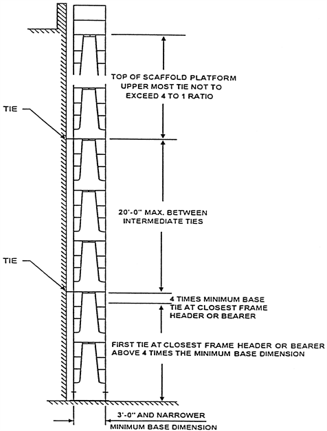
MAXIMUM VERTICAL TIE SPACING 3'-0" AND NARROWER BASES
 |
SYSTEM SCAFFOLD
 |
 |
TUBE AND COUPLER SCAFFOLD
 |
SCAFFOLDING WORK SURFACES
 |
OUTRIGGER SCAFFOLD
 |